
")
COUPLE OF STAGE-MOUNTED DISPERSERS
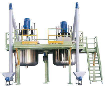 CONSTRUCTION FEATURES
- Metal bearing structure in carbon steel sections and tubing
- Independent access ladder, with rails and feet-support, and front sliding rail
- Two AISI 304 stainless steel mixing vessels with three 120° support frames
- Carbon steel and/or AISI 304 stainless steel self-bearing lid with proper couplings for powder and fluid loading, and dust extraction pipes
- Lifting of motor heads by power unit and hydraulic distributor that can be operated with two different movements to ensure against accidental starting
- Lifting piston with check valves and flow control
- High-build chrome-plated stirring shafts
- Direct drive
- Cowless Aisi 304 stainless steel or chrome-plated impellers
- Switch board with Inverter control with disturbance filter
- Control panel of standard or explosion-proof type
- Heavy-duty or explosion-proof motor with thermistors
- Two gearmotor-driven scrapers (approx. 8 rpm)
- Mobile lid section for vessel access with safety limit switch to ensure that the machine is not started when the lid is up
- Safety systems and CE mark
FUNCTIONS
All electric controls and warning devices are placed on the Control Panel of the Disperser couple.
The hydraulic-operated head lifting distributor is located on the machine body: it must be operated after pressing the ON push-button of the hydraulic power unit motor on the Disperser control panel.
The Control Panel also features: the potentiometer for continuous stirring shaft speed adjustment, digital rev-counter with display, the ON-OFF-RESET push-buttons for Inverter control and the EMERGENCY button. The Switch Board with the Inverter features the following controls:
- Power switch to set the machine on
- Thermal cut-out, mains voltage, thermistor protection lights
- Emergency button
OPERATION AND MAINTENANCE
- Low energy consumption: power consumption depends on the power actually supplied by the Inverter by turning the power-knob
- Low noise
- Easily accessible and easy-to-use controls
- Easy access to mixing vessels for maintenance and/or replacement of vessels, of scrapers or just for cleaning
- Easy access to the power unit, normally located under the feet-support of the Disperser Couple Stage and anchored on a proper bracket on the support leg between the two mixing vessels.
ALTERNATIVE VERSIONS
- Flat or convex Aisi 304 stainless or carbon steel vacuum-tight lid, vacuum-pump connections, connections for fluid loading, inspection port.
- Dual Inverter power supply (one single Inverter in the basic model)
- Lifting with two hydraulic power units. This feature, together with the dual Inverter, makes the two Dispersers totally independent of each other.
- Automatic and/or manual powder and fluid loading
- 6 and 8 pole motor (4 pole motors are normally employed
- Continuous motor cooling at low duty with servoventilation
- Head lifting/lowering with Control Panel push-buttons and solenoids on the hydraulic power unit (instead of a hydraulic distributor installed on the machine)